
Rl Rc Rlc Series And Parallel Circuits Circuit Diagram
Fig. 8.21 (a) A voltage-step function is shown as the source driving a general network. (a) A voltage-step forcing function is shown as the source driving a general network. (b) A simple circuit which, although not the exact equivalent of part (a), may be used as its equivalent in many cases. (c) An exact equivalent of part (a).
RC RLC RL Series Circuits Your Electrical Guide
RC, RL and RLC Circuits . 0. 2 4 6 8 10 0 2 4 6 8 10 12 14 18 20 t V V0 1/2 V0 T1/2 Figure 4: Discharge of a capacitor. Procedure y Assemble the circuit shown in Figure 5. Function Generator. Oscilloscope R = 10 kΩ C = 0.1 μF Red Black Red Black Figure 5: Investigating an RC circuit . y With initial values R = 10 kΩ, C = 0.1 µF, and f = 100.
Offset problem in simulating current and voltage phase relation of parallel rlc circuit, Is it a
RC, RL, and RLC Circuits 5 Procedure • Measure the half-life, T 1/2 and from this compute the time constant τ using Equation 3. • Compute the value of RC from component values. Note that, as described above, the square-wave generator has an internal resistance of 50 Ω. Thus
What Is The Power Factor Of Rl Circuit Wiring Diagram
The RLC circuit analyzed here is the parallel form. The solution to the natural response emerges from this long analysis. The answer is not a simple single exponential equation like we get for RC, but rather a choice of three different responses ("variations") depending on the value of R, L , and C.

RC, RL and RLC Circuit Basic Principle and Circuit Explanations
Experiment 6: Ohm's Law, RC and RL Circuits OBJECTIVES 1. To explore the measurement of voltage & current in circuits 2. To see Ohm's law in action for resistors 3. To explore the time dependent behavior of RC and RL Circuits PRE-LAB READING INTRODUCTION When a battery is connected to a circuit consisting of wires and other circuit elements
AllSingingAllDancing RLC circuit Engineering Teaching
The Series RLC Circuit Impulse response of RC Circuit. Let's examine the response of the circuit shown on Figure 1. The form of the source voltage Vs is shown on Figure 2. Vs R C vc +-Figure 1. RC circuit t Vp 0 tp Vs Figure 2. We will investigate the response vc(t) as a function of the τp and Vp. The general response is given by: () 1 0 t.
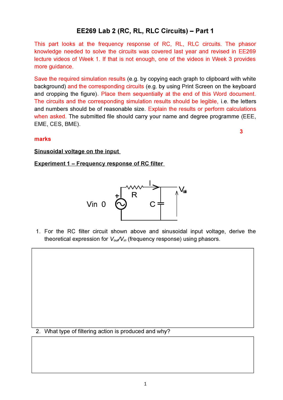
EE269 RC, RL and RLC Circuits Part 1 EE269 Lab 2 (RC, RL, RLC Circuits) Part 1 This part
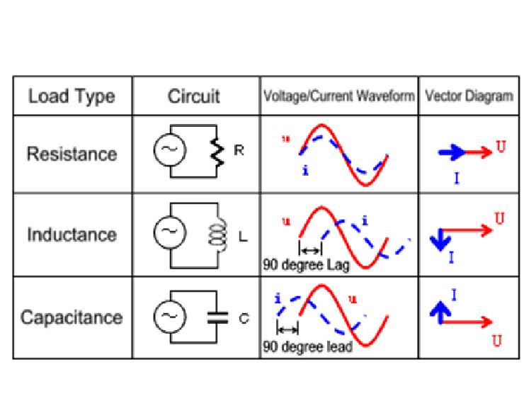
Basic Principle of RC/RL and RLC circuits: Before we start with each topic let us understand how a Resistor, Capacitor and an Inductor behave in an electronic circuit. For the purpose of understanding let us consider a simple circuit consisting of a capacitor and resistor in series with a power supply (5V). In this case when the power supply is.
montage rlc Aep22
Two-element circuits and uncoupled RLC resonators. RLC resonators typically consist of a resistor R, inductor L, and capacitor C connected in series or parallel, as illustrated in Figure 3.5.1. RLC resonators are of interest because they behave much like other electromagnetic systems that store both electric and magnetic energy, which slowly.

Image result for rl circuit formula
Learning Objectives. After completing this chapter, you should be able to: Identify series-only and parallel-only sub-groups in series-parallel RLC networks. Compute complex equivalent impedance for series-parallel RLC circuits. Simplify an entire RLC network into a simple series or parallel equivalent comprised of complex impedances.

RL, RC, and RLC Circuits Natural vs Forced Response
Time Constant τ "Tau" Equations for RC, RL and RLC Circuits. Time constant also known as tau represented by the symbol of " τ" is a constant parameter of any capacitive or inductive circuit. It differs from circuit to circuit and also used in different equations. The time constant for some of these circuits are given below:
RL, RC, AND RLC CIRCUITS
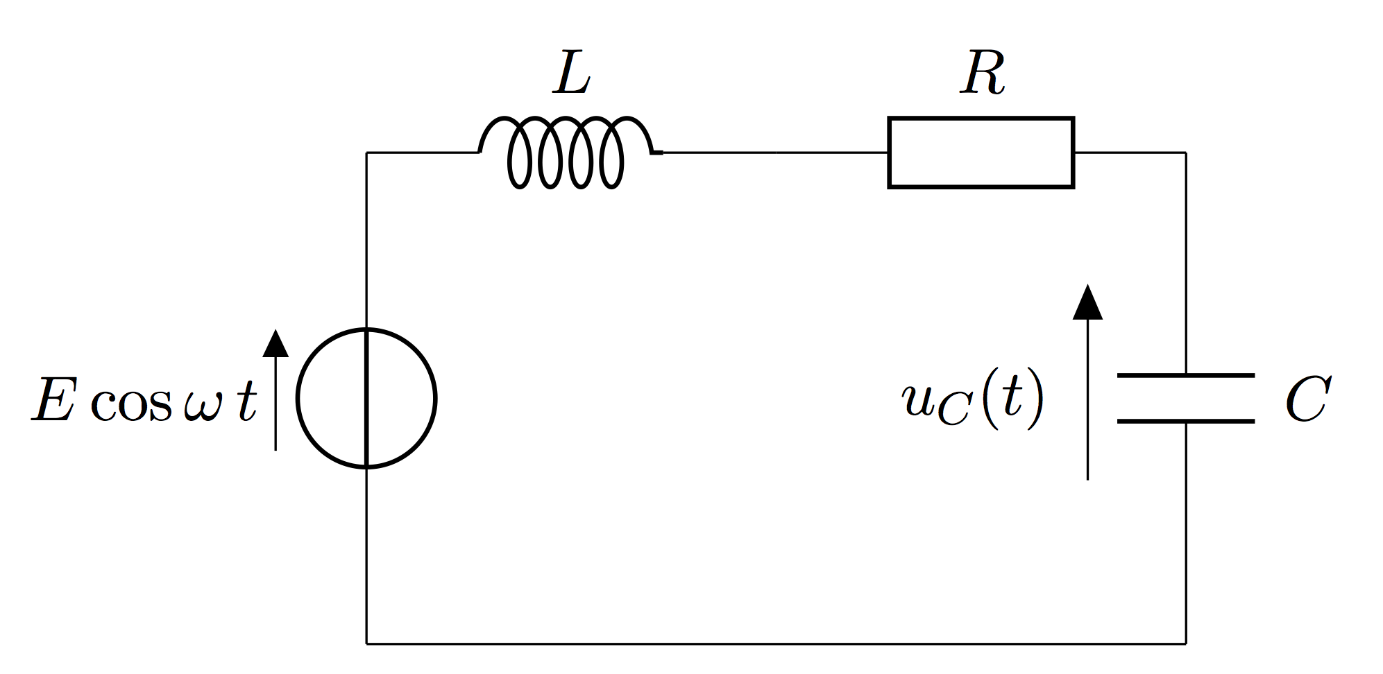
An RLC circuit is an electrical circuit consisting of a resistor (R), an inductor (L), and a capacitor (C), connected in series or in parallel. The name of the circuit is derived from the letters that are used to denote the constituent components of this circuit, where the sequence of the components may vary from RLC.. RC circuit; RL circuit.

Phasor Diagram For Rlc Series Circuit Circuit Diagram www.vrogue.co
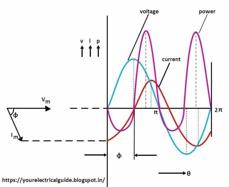
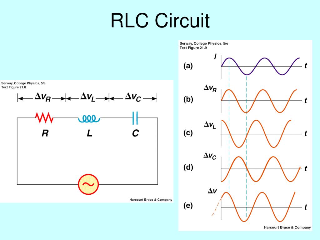
When X L > X C, the phase angle φ is positive. In this case, RLC series circuit behaves as an RL series circuit. The circuit current lags behind the applied voltage and power factor is lagging. In this case, i = Im sin (ωt - φ). When X L < X C, the phase angle φ is negative. In this case, the RLC series circuit behaves as an RC series.

Inductors In Series And Parallel Pdf
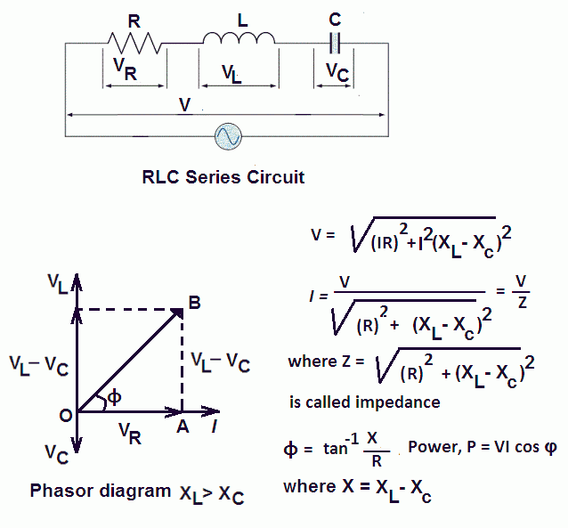
Series RLC Circuit Example No1. A series RLC circuit containing a resistance of 12Ω, an inductance of 0.15H and a capacitor of 100uF are connected in series across a 100V, 50Hz supply. Calculate the total circuit impedance, the circuits current, power factor and draw the voltage phasor diagram. Inductive Reactance, XL. Capacitive Reactance, XC.

SOLUTION Rl rc rlc circuits Studypool
This page titled 1: Introduction to RL and RC Circuits is shared under a CC BY-NC-SA 4.0 license and was authored, remixed, and/or curated by James M. Fiore via source content that was edited to the style and standards of the LibreTexts platform; a detailed edit history is available upon request.

Time Constant τ “Tau” Formulas for RC, RL & RLC Circuits Time constant, Circuit, Electronic
A circuit with resistance and self-inductance is known as an RL circuit. Figure 14.5.1a 14.5. 1 a shows an RL circuit consisting of a resistor, an inductor, a constant source of emf, and switches S1 S 1 and S2 S 2. When S1 S 1 is closed, the circuit is equivalent to a single-loop circuit consisting of a resistor and an inductor connected across.
impedance of parallel rlc circuit
Goal: Measure the time constant of an RC and an RL circuit, compare to the theoretical calculations. Use the schematics of figure 2 and 3 as your circuits. Figure 3: R-L circuit driven by an ideal step Voltage source. V IN can undergo a step change from zero to V IN or from V IN to zero Procedure: a.