
Physics Clip Art Cliparts.co
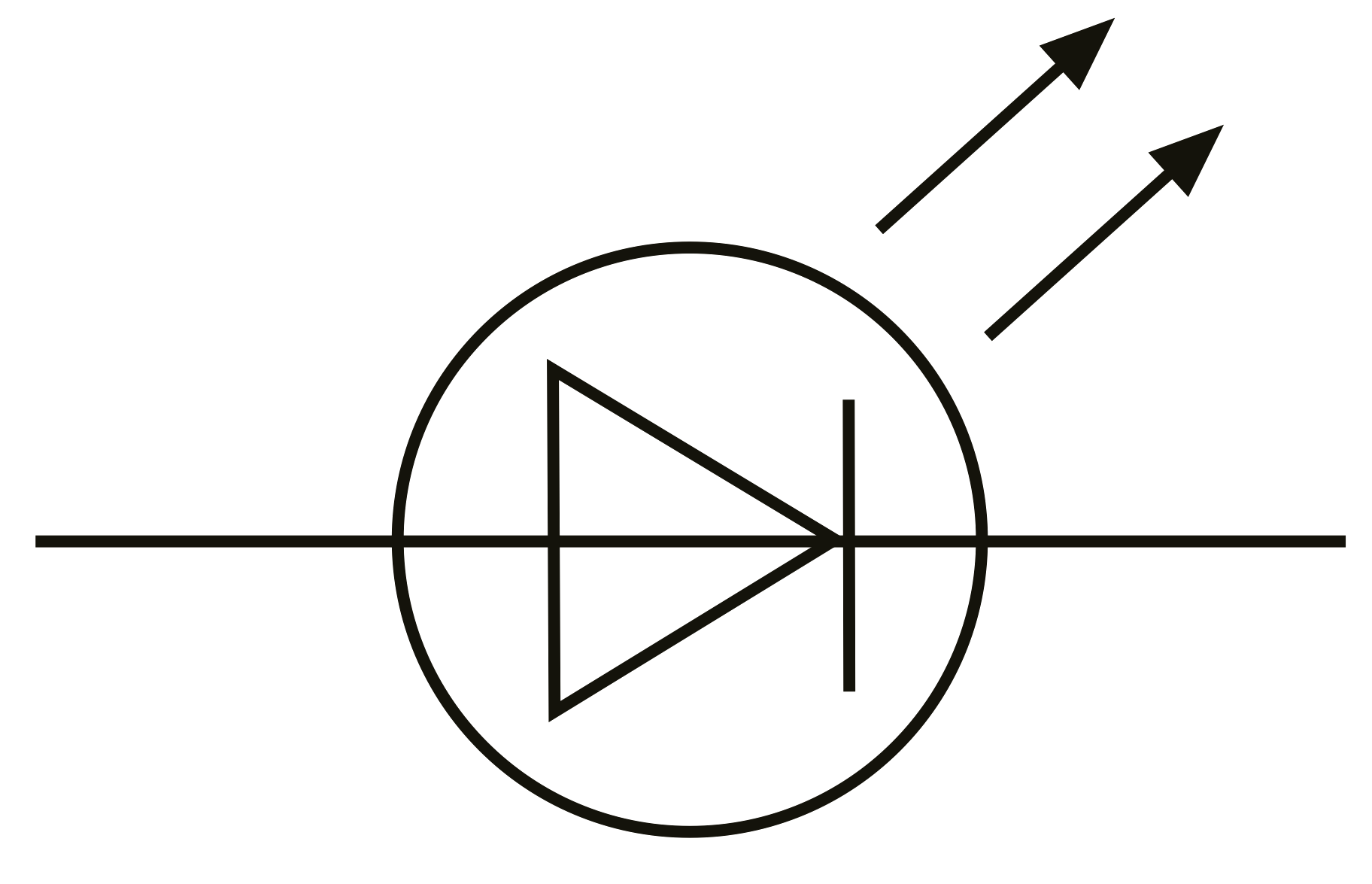
The electric schematic symbol for an LED is based on that of a diode. It is distinguished from the symbol for a regular diode by the presence of two arrows indicating the emission of light. LED Efficiency and Usage. LEDs are amazing because the light they produce is of a narrow band. As a comparison, incandescent bulbs produce light along a.
Schematic Symbol Of Led ubicaciondepersonas.cdmx.gob.mx
A the connecting leads or pins of a component in a schematic diagram can be identified using letters or abreviations. For example, the connecting leads of a bipolar junction transistor, (BJT) are identified as E (emitter), B (base), and C (collector).

E2 Lab 2
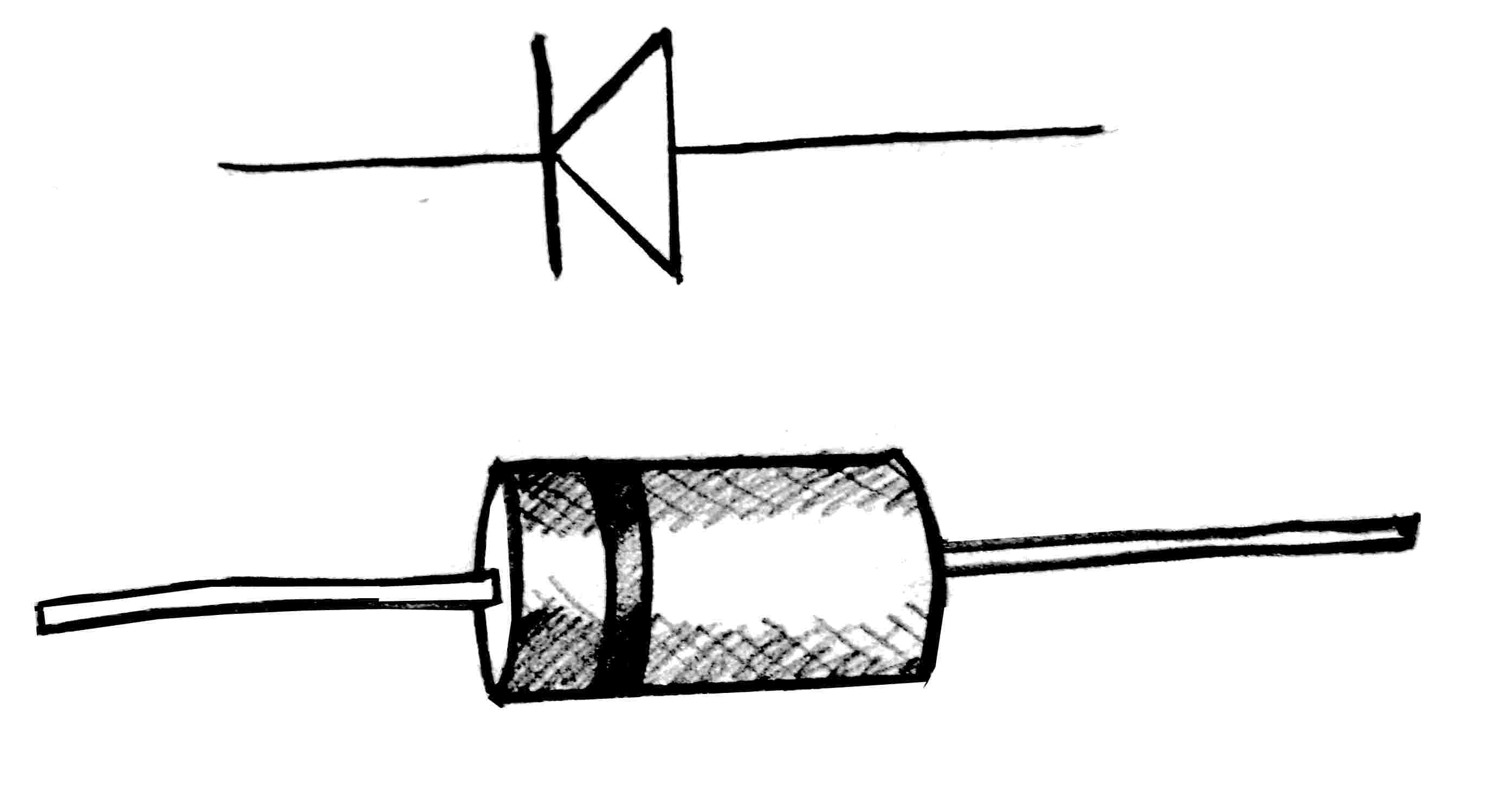
The terminals of a diode are called the anode and the cathode; a schematic symbol for a diode is shown in Fig. 1. Diodes are intended to conduct current from the anode to the cathode. Diodes have a minimum threshold voltage (or Vth , usually around 0.7V) that must be present between the anode and cathode in order for current to flow.
Led Circuit Diagram Symbol ClipArt Best
Light Emitting Diode (LED) Created on: 30 July 2012 The LED (Light Emitting Diode) is exactly what it name suggests - a diode that emits light. LEDs are like small light bulbs and are available in different sizes and colours. Examples of LEDs used in Electronics LED Symbol The symbol for an LED used in circuit diagrams is shown here: LED Polarity

Led Schematic Symbol ClipArt Best
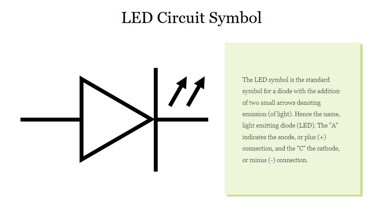
The LED symbol is the standard symbol for a diode with the addition of two small arrows denoting emission (of light). Hence the name, light emitting diode (LED). The "A" indicates the anode, or plus (+) connection, and the "C" the cathode, or minus (-) connection.
Led Electrical Symbol ClipArt Best
Today we will Learn about LED Logic Symbol Creation with Cadence Tool.What is an LED? In the simplest terms, a light-emitting diode (LED) is a semiconductor.

LED Circuit Symbol ClipArt Best
LEDs have a similar circuit symbol to diodes. They look like this: LED circuit symbol One important thing to remember for LEDs is that polarity matters. If you put an LED the wrong way on a circuit, it won't light up and will block current through that path. It won't break though if it is powered on while backwards like electrolytic capacitors.
Led Schematic Symbol ClipArt Best
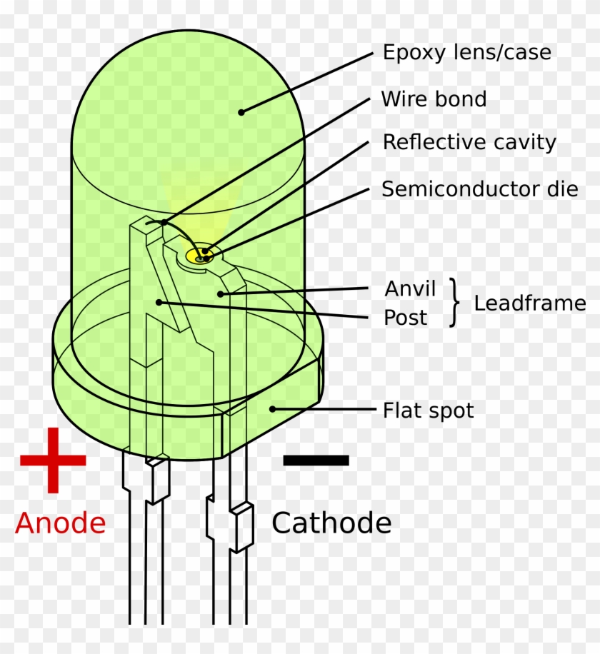
The only difference between a diode and an LED in the schematic is the arrows added over the symbol. They represent the light being emitted from the diode. If you take a closer look at an LED, you will see it's made of several parts. The case or housing of the LED is usually made from epoxy or plastic material.

Symbol For Led ClipArt Best
Electrical symbols & electronic circuit symbols of schematic diagram - resistor, capacitor, inductor, relay, switch, wire, ground, diode, LED, transistor, power supply, antenna, lamp, logic gates,.

Light Emitting Diode Symbol ClipArt Best
Parts of a conventional LED. The flat bottom surfaces of the anvil and post embedded inside the epoxy act as anchors, to prevent the conductors from being forcefully pulled out via mechanical strain or vibration. Close-up of an LED with the voltage being increased and decreased to show a detailed view of its operation.

Schematic Symbol For Led ClipArt Best
The " Light Emitting Diode " or LED as it is more commonly called, is basically just a specialised type of diode as they have very similar electrical characteristics to a PN junction diode. This means that an LED will pass current in its forward direction but block the flow of current in the reverse direction.

Component symbol of led Schematic Symbol Of Led Symbol Of
A light Emitting Diode (LED) is an optical semiconductor device that emits light when voltage is applied. In other words, LED is an optical semiconductor device that converts electrical energy into light energy.

Eliminator Blog Schematic Symbol Of Led
A light-emitting diode (LED) is a semiconductor device that emits light when an electric current flows through it. When current passes through an LED, the electrons recombine with holes emitting light in the process. LEDs allow the current to flow in the forward direction and blocks the current in the reverse direction.
Component Led Diagram Symbol Wiring Single Digit Seven Diagram Of An
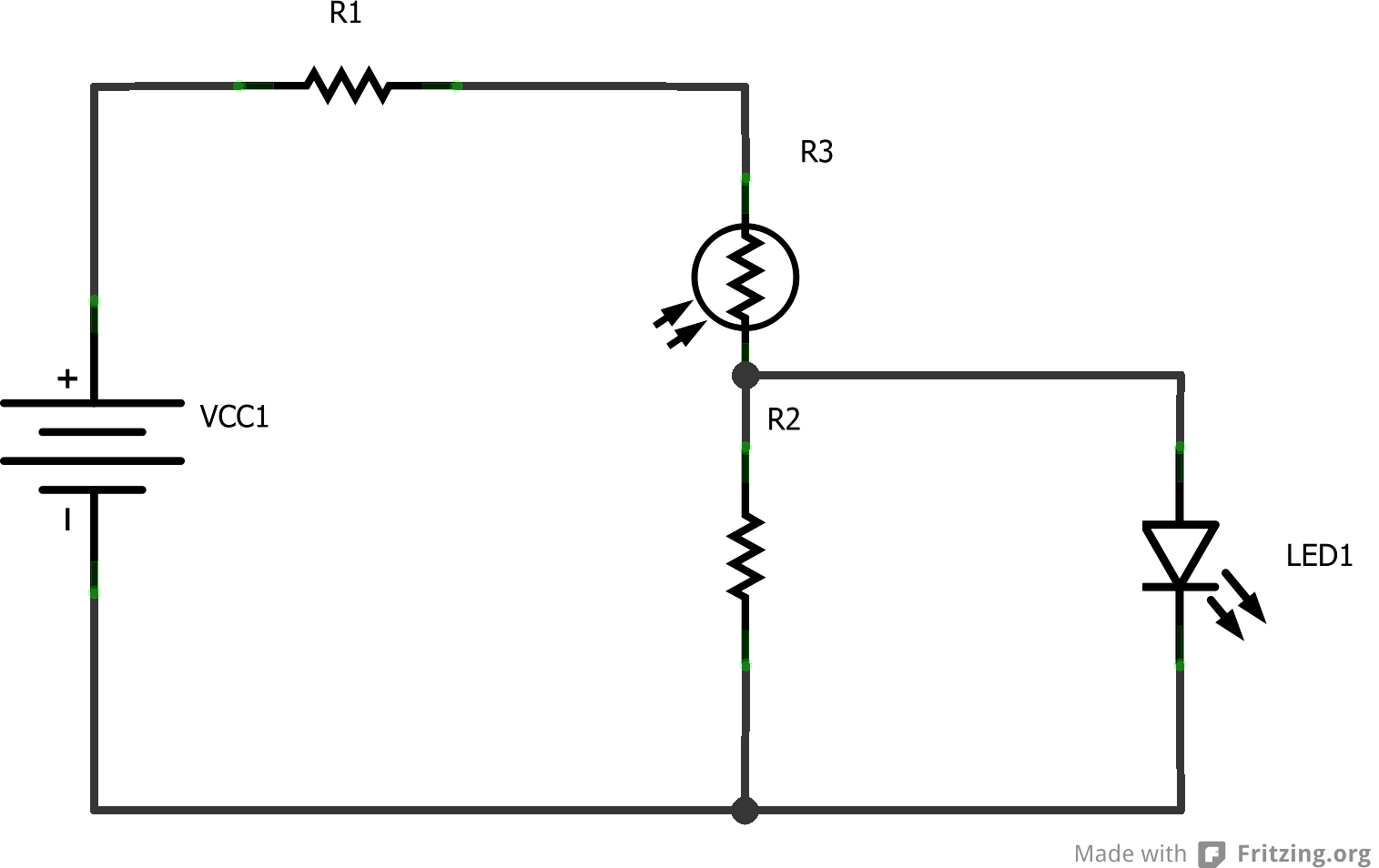
In electronics, an LED circuit or LED driver is an electrical circuit used to power a light-emitting diode (LED). The circuit must provide sufficient current to light the LED at the required brightness, but must limit the current to prevent damaging the LED.

Simple Led Circuit Diagram ,Find Here
V - LED forward bias voltage. I - Current. LED Circuit. The commercially used LED's have a typical voltage drop between 1.5 Volt to 2.5 Volt or current between 10 to 50 milliamperes. The exact voltage drop depends on the LED current, colour, tolerance, and so on. LED as an Indicator. The circuit shown below is one of the main applications.

Led Symbol In Circuit ClipArt Best
Below is a standard diode, a Zener diode, a Schottky diode, and a Light-Emitting Diode (LED). Different diode symbols Schematic Symbols of a Transistor The most common transistor types are the Bipolar Junction Transistor (BJT), Darlington Transistor, and Field-Effect Transistor (FET). The schematic symbols for these types are shown below: